Active Pitch Control Aerial-Aquatic Robot
Overview
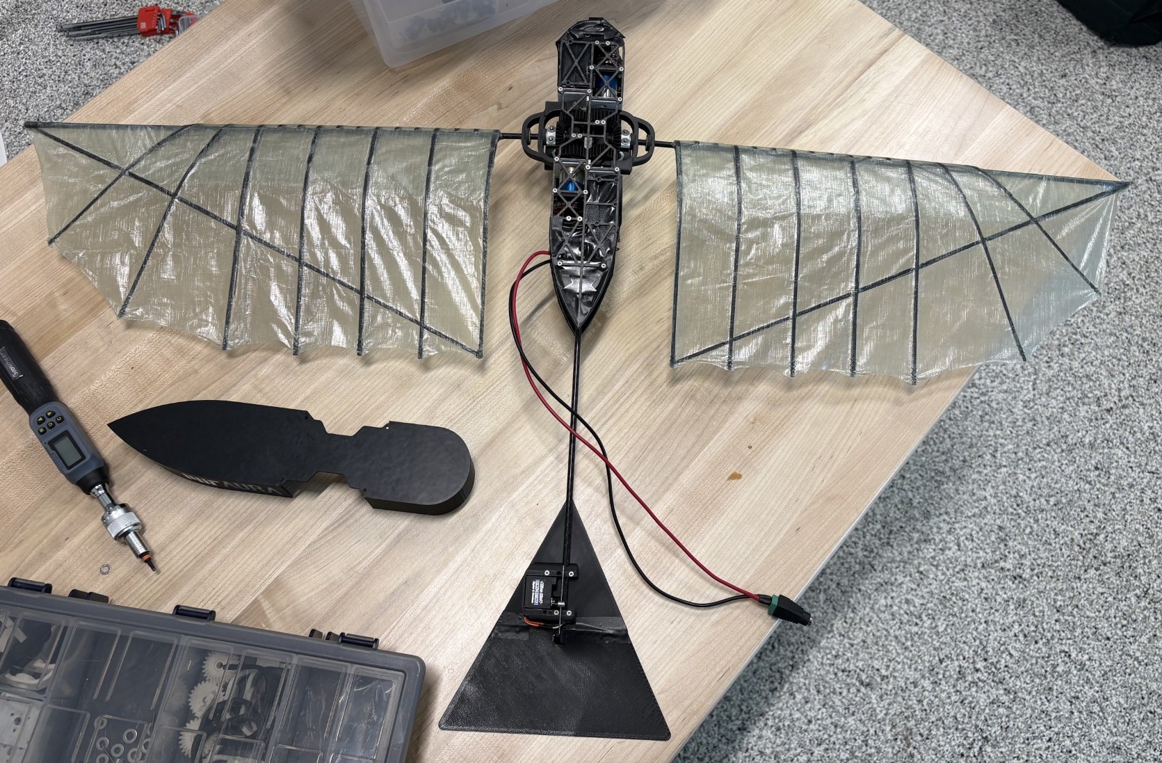
Over two semesters of research in the AURA Lab during my junior year, I designed, manufactured, and tested a two-winged flapping-wing robot with active pitch control. The robot features a differential gearbox that enables pitch control through dual DC motor oscillation. Testing of the custom gearbox showed an 8% power loss at 5 Hz, validating the gearbox design. Thrust testing demonstrated more than 28% increased thrust at 3.5 Hz flapping frequency compared to the lab's single wing robot. I am continuing to improve the robot to withstand more aggressive testing conditions. Future flapping tests in both air and water will eventually enable free flight and swimming. This robot will hopefully be the first flight-capable flapping-wing robot with integrated pitch control.
Motivation
Flapping-wing robots combine the efficiency of fixed-wing flight with the maneuverability of propeller-based systems. The ability to transition between air and water with a single robot enables applications in environmental and biological monitoring, coastal search-and-rescue, and aquatic ecosystem exploration.
Bird flight mechanics and prior research projects suggest that introducing active wing pitch control can improve efficiency and controllability across different flight regimes. Single-wing experiments in the AURA Lab demonstrated a significant improvement in thrust-to-power ratio with active pitch control. A two-winged robot with four independent servos confirmed that pitch control can alter force production in air, but was too heavy for flight. No prior work has produced a flight-capable flapping-wing robot with active pitch control.
This project sought to fill that gap by designing and testing a flight-capable two-winged robot with active pitch control. Current and future test results with this prototype would be a substantial advancement of flapping-wing robotics, specifically on our understanding of efficiency and controllability while flying and swimming.
Design
Gearbox
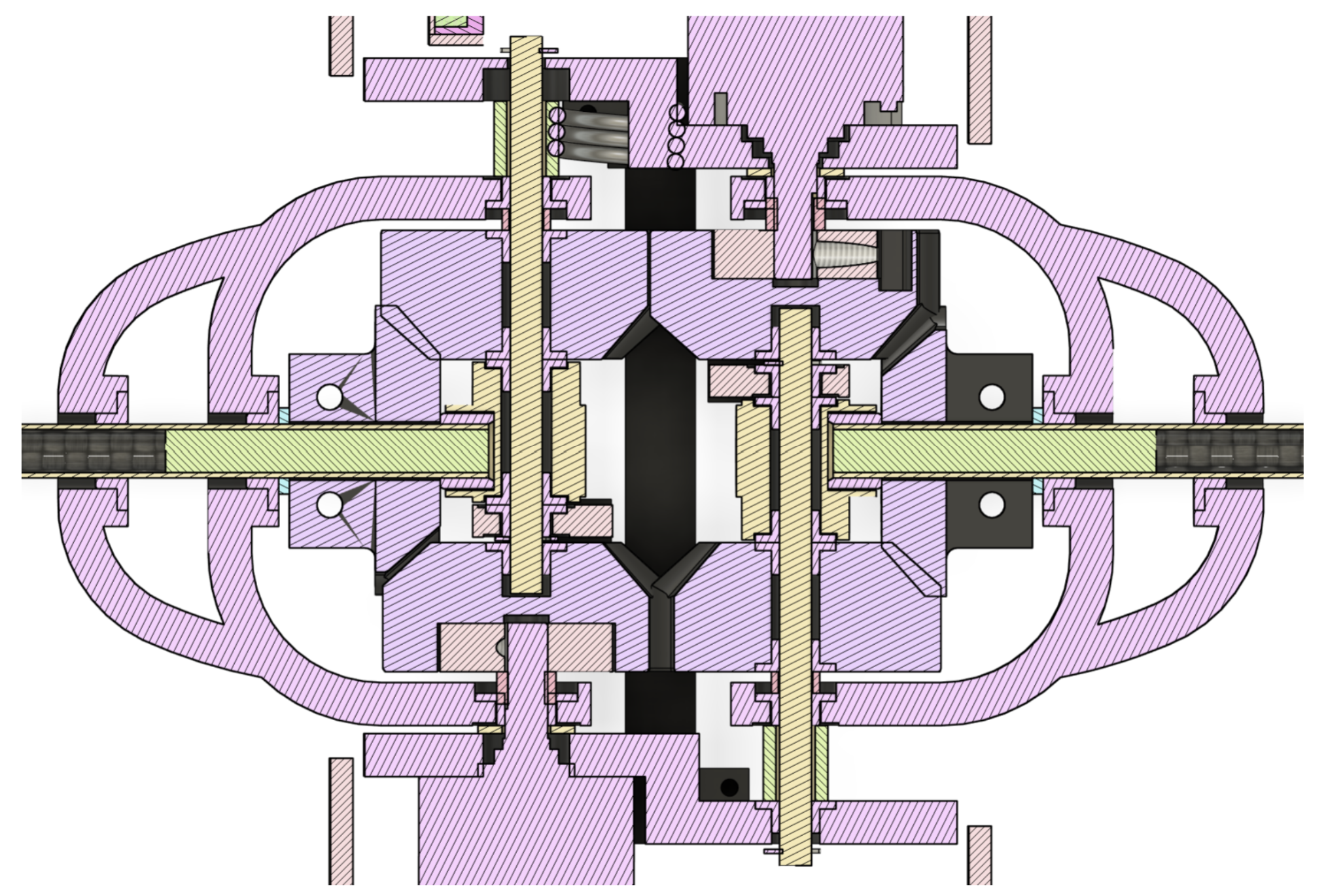
The differential gearbox is the most mechanically complex element of the robot. The bevel gear arrangement allows pitch control by oscillating the motors themselves, eliminating the need for additional oscillating mechanical components. This was selected as the method of introducing pitch because it limits the number of necessary actuators, provides high controllability of the flapping parameters, and produces a lightweight, compact design.
Direct driving the gearbox was preferred over couplings to avoid alignment issues, added weight, and increased length in the robot. The reduction shaft is somewhat cantilevered as a result, which was mitigated by the free-spinning shaft on the opposite side acting as a pseudo-support.
The design provides room for spring element integration, enabling future resonance-based efficiency improvements seen in the single-wing prototype. A bracketed wing support attaches to both shafts, constraining the external gear and reducing wing shaft deflection.
All rotating elements use high-speed, high-temperature plastic bushings rather than bearings to save weight and resist water corrosion. The body consists of two carbon fiber plates with modular internal elements, providing a rigid, lightweight, and iterable structure. Trusses were added at critical locations for stiffness.
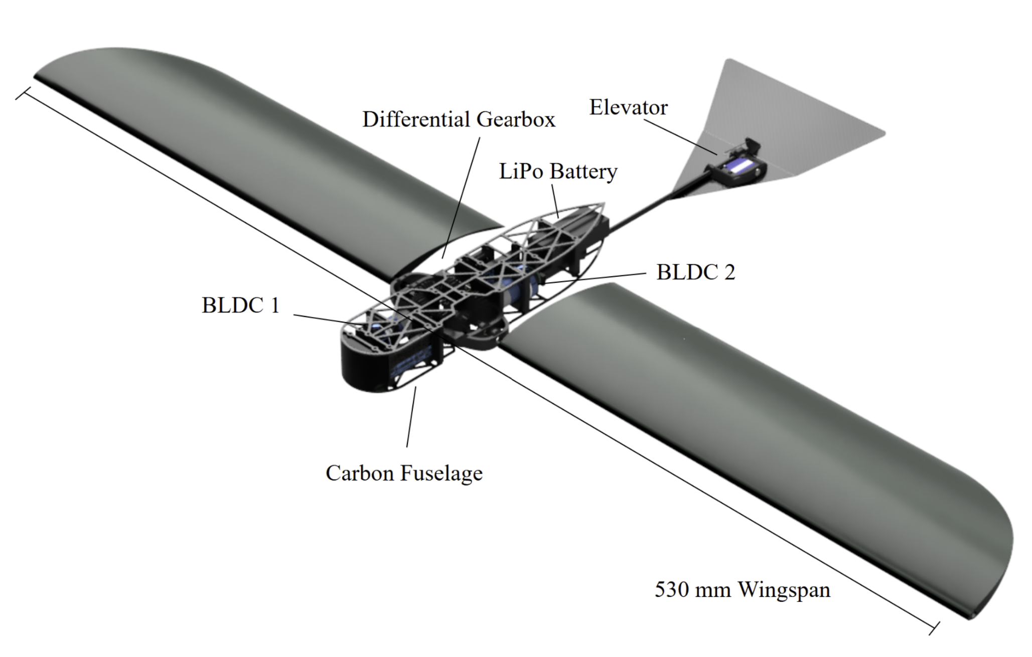
Mass & Wings
Component masses were estimated by weighing third-party parts and calculating custom part weights using material densities. The battery attachment position was chosen to allow center-of-mass adjustment around the quarter chord, following the approach used in previous research for stable flight.
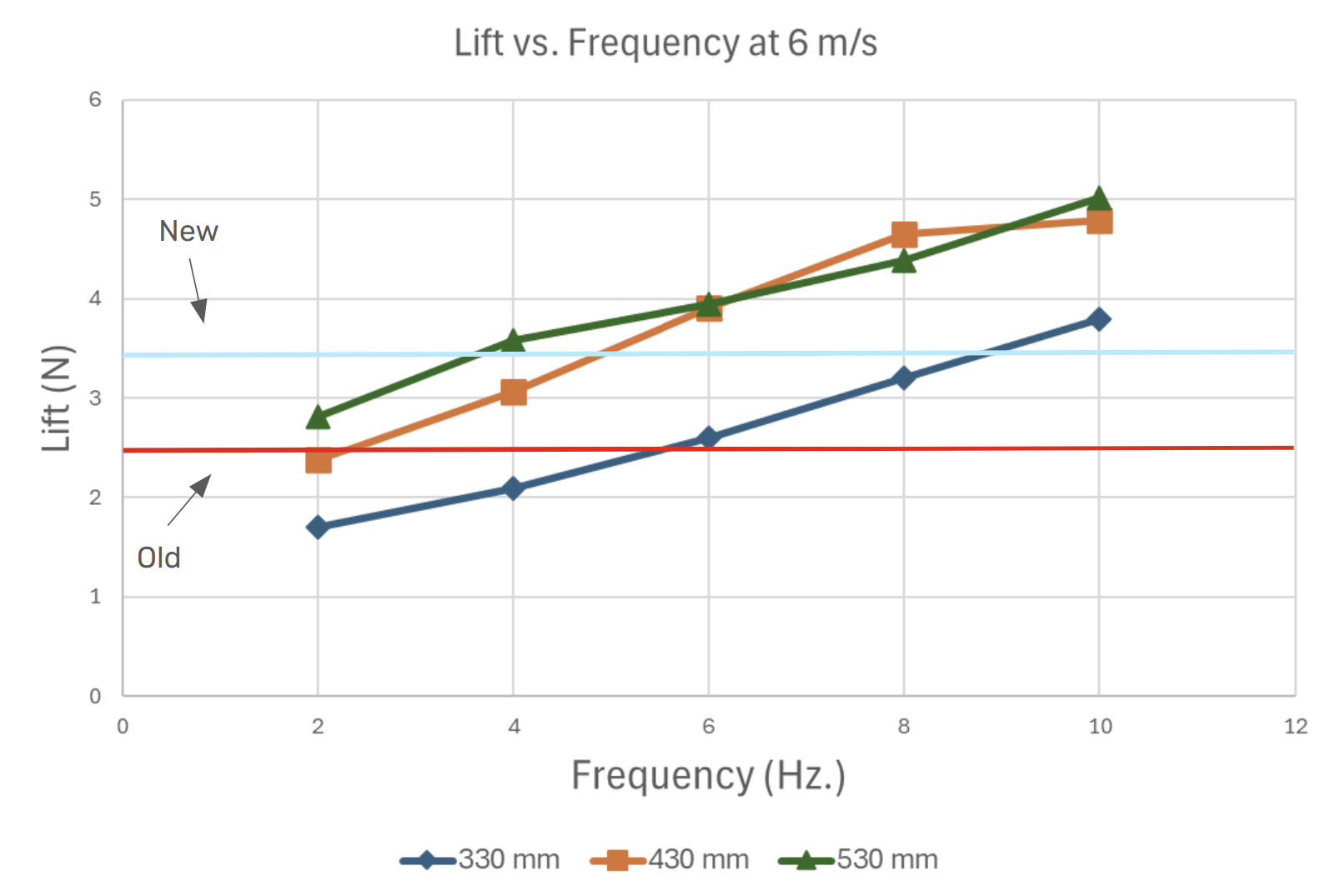
The 530 mm wings were sized using lift and thrust data from a fixed wing robot to guarantee lift/weight and thrust/weight greater than 1 at 5 Hz to enable flight.
Manufacturing
Machining & 3D Printing
The free-spinning shaft was turned on a manual lathe and grooved for e-clips. The internal press-fit component was machined on a CNC mill from aluminum. The majority of manufacturing is additive: gearbox gears and structural supports were printed on the Markforged printer in Onyx for high print resolution and strength. The carbon fiber body plates were cut on a waterjet.
Electronics & Software
The robot uses two ESCs connected to a microcontroller. The microcontroller communicates with the ESCs via RX/TX serial, sending desired motor angles based on current flapping parameters. A Python communication script sends flapping trajectory commands and records motor and current data during experiments.
Testing
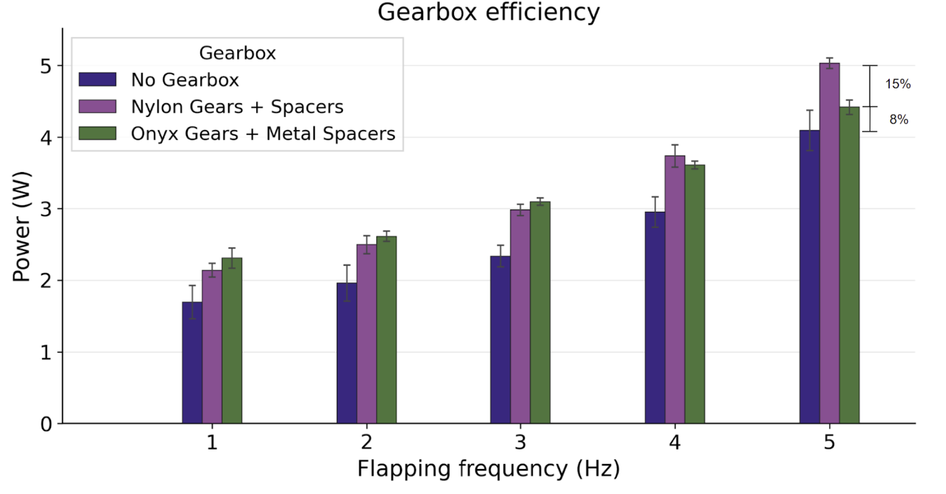
Gearbox Efficiency
The first test sought to quantify frictional losses in the gearbox with no wing load as a measure of gearbox efficiency. Tests were run at 0.5 Hz increments from 0 to 5 Hz with 30 degree flapping amplitude and 21 degree pitch amplitude, the optimal thrust production condition. Both Nylon and Onyx gearbox configurations were tested.
The Onyx gearbox showed 8% power loss at peak frequency, an acceptable level that validates the design and manufacturing of the gearbox. At lower frequencies the Nylon gearbox performed marginally better, but at higher frequencies the Onyx gearbox was significantly more efficient, attributed to higher gear print resolution, reduced spacer compliance from metal spacers, and lower friction between metal and plastic. Given the much higher loads during actual flapping, the Onyx configuration was the clear choice.
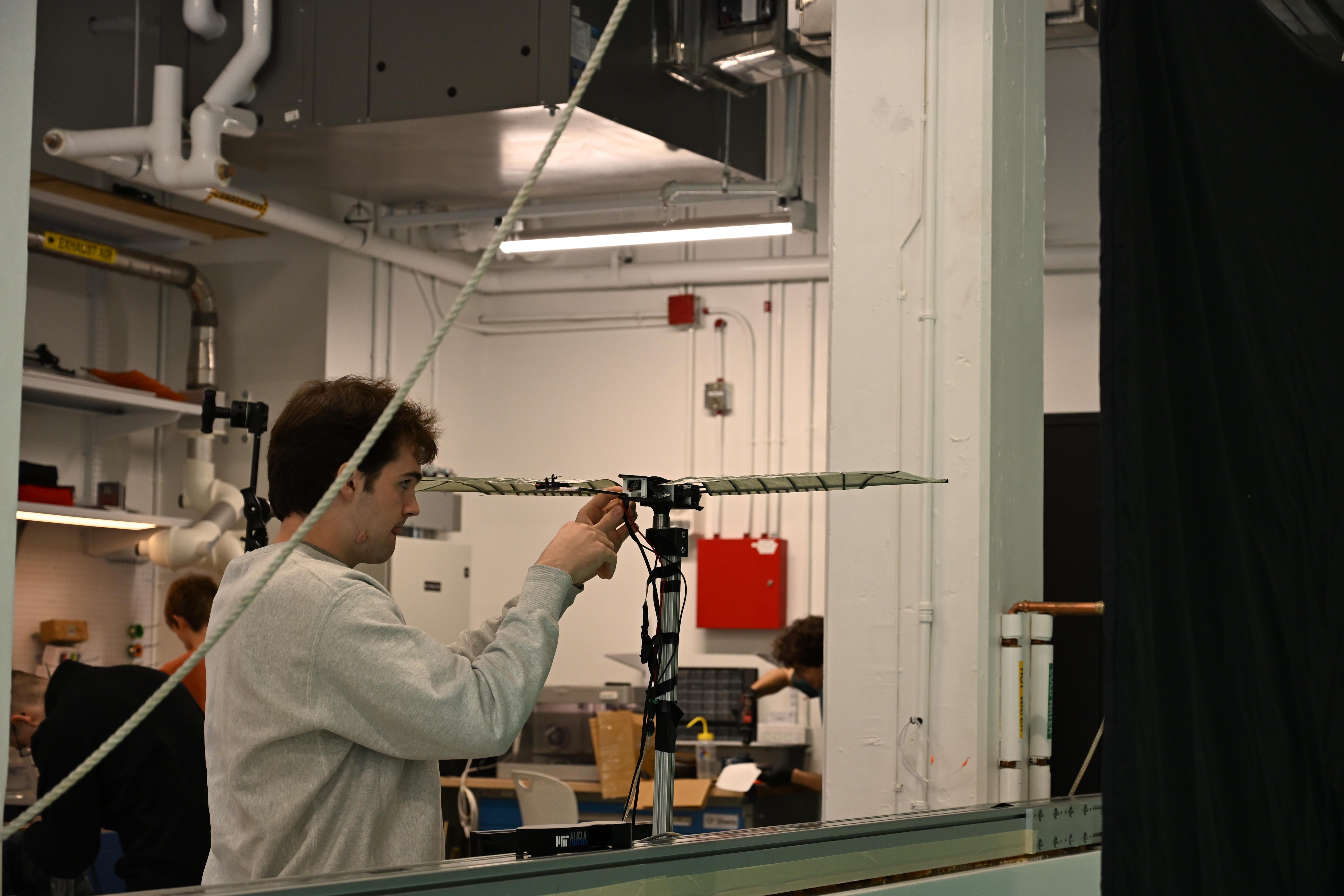
Thrust Testing
The robot was mounted on a six-axis load cell and tested at the same thrust-optimal conditions from 0 to 5 Hz. The optimal thrust parameters were chosen due to the testing being done with no wind flow, where thrust provides the most relevant force production data and puts the highest loads on the gearbox, acting as a stress test. During initial testing, the outer gear skipped two teeth at 3.5 Hz due to insufficient stiffness in the wing support, which caused the wings to contact the body. The wing support was thickened and printed with continuous carbon fiber reinforcement, significantly increasing stiffness.
In the second test series, failure occurred at 4 Hz from three concurrent issues: wing shaft slippage due to deformability of the thin press-fit piece, the wing base popping out of the root support under high bending loads, and insufficient controller gain for the two-wing load at frequencies above 3.5 Hz. Each of these has a clear path to resolution: a thicker press-fit piece, an ovular root support for increased bending resistance in the primary loading direction, and increased controller gains with thermal management for the motors.
Despite these limitations, the results showed more than 28% increased thrust at 3.5 Hz compared to the lab's fixed-wing robot. The thrust-to-power ratio is lower but comparable. Future integration of spring elements to exploit resonance is projected to improve the thrust-to-power ratio by an additional 30%, bringing the prototype to the same efficiency while offering significantly greater control over force production.
Next Steps
The immediate next steps are to address the identified mechanical and electrical issues to enable stable 5 Hz flapping. Once achieved, air tests at multiple wind speeds and flapping conditions will follow, largely mirroring the single-wing test protocol. Water tests via tow tank will require waterproofing and will introduce further design iterations.
With full air and water force production data in hand, control algorithms can be developed for free flight and swimming, and appropriate launch platforms can be designed. This will culminate in the first flight-capable flapping-wing robot with active pitch control, advancing understanding of the efficiency and controllability benefits of wing pitch in flapping-wing robotics.