Rocket Engine Nitrogen Pressurization
Overview
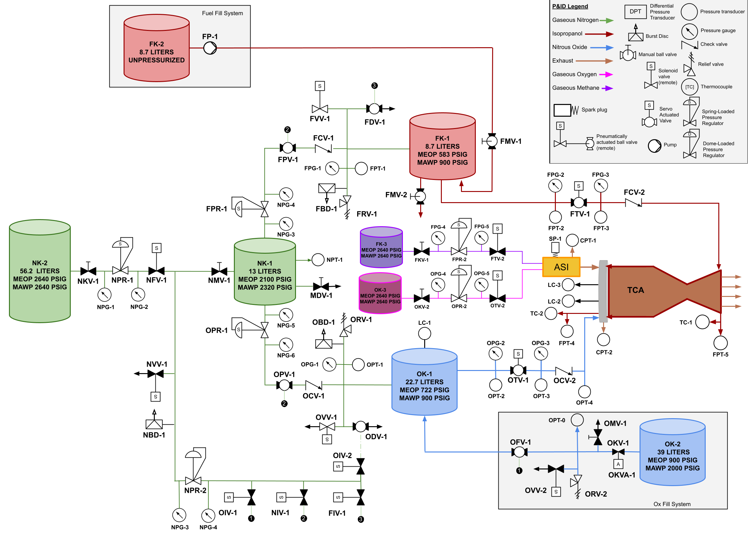
The MIT Liquid Propulsion and Controls team designed and built a bipropellant liquid rocket engine using nitrous oxide and IPA with nozzle thrust vector control. As a member of the fluids systems team, my primary responsibility was sizing the tanks and selecting the valves for the back pressurization system using nitrogen gas. Back pressurization was used to ensure consistent injection pressure of the fuel and oxidizer, maintaining a stable burn.
The green elements on the P&ID represent the nitrogen back pressurization system.
Design
Tank Sizing
Without nitrogen back pressurization, nitrous oxide evaporates as liquid leaves the tank in order to maintain vapor pressure. This evaporation cools the remaining liquid, which lowers its vapor pressure, progressively reducing the pressure driving the flow. With nitrogen added, nitrous oxide still evaporates as liquid leaves, since its partial vapor pressure depends on the amount of nitrous gas and the volume it occupies rather than the total pressure. This continued evaporation still causes the liquid to cool and its vapor pressure to drop, but the total tank pressure is maintained by the nitrogen, keeping injection pressure consistent.
As liquid nitrous leaves, the nitrogen must expand to fill the added volume and also increase its partial pressure to compensate for the dropping nitrous vapor pressure. I used two bounding approaches to size the nitrogen system: a conservation of mass isothermal model and a conservation of energy adiabatic model. The isothermal case ignores work from gas expansion, making the adiabatic case a more conservative bound. Both were used to determine the final pressure in the nitrogen tank, which must remain above the required fuel and oxidizer tank pressures throughout the burn to ensure continuous flow.
Since this engine will eventually be incorporated on a launch platform, a minimum volume scuba tank was selected to drive the back pressurization system. The scuba tank volume and pressure was chosen to be 13L at an initial pressure of 2100 psi, filled from an off-the-shelf T cylinder. The same methods were applied to size this supply cylinder, accounting for the energy lost as nitrogen transfers from the cylinder to the scuba tank, ensuring the cylinder could fill the tank to the required initial pressure.
Valve Selection
Valves were selected based on the type of control required at each point in the system. Spring-regulated valves were chosen between the cylinder and scuba tank and between the scuba tank and the propellant tanks to allow precise control over the various operating pressures. Pneumatically actuated valves were paired with servo-actuated valves on a lower pressure nitrogen line to serve as remote shutoffs for the main line. The system also included check valves, relief valves, and burst discs as additional safety measures. I also selected pressure gauges and transducers and determined their locations to capture pressure data at critical points throughout the system. The back pressurization system was modelled using the Colebrook-Haaland and Darcy-Weisbach equations to calculate pressure drop through each component, enabling tubing sizing and confirming that the selected valves could deliver sufficient high-pressure flow to meet injection pressure requirements.
Results
The engine has undergone successful dry runs and a hot fire attempt, with back pressurization values meeting predictions throughout. The ignition sequence has not yet produced a successful burn, though the pressurization system performed as designed. Using conservative bounding methods adds a margin of safety to the design.