Flexures for Artificial Muscle Testing
Overview
For my sophomore year research project, I worked with a graduate student designing flexures to test the force-displacement characteristics of artificial muscles for potential robotic application. The flexures allowed attachment and flexing of an artificial muscle, measuring its force production and displacement through flexure deflection. I explored using an adjustable boundary condition to create a linearly varying stiffness flexure and proved the validity of the concept that was eventually incorporated into these flexures. I also designed and machined a vacuum chuck used on the desktop mill to cut the flexures.
Adjustable Boundary Condition
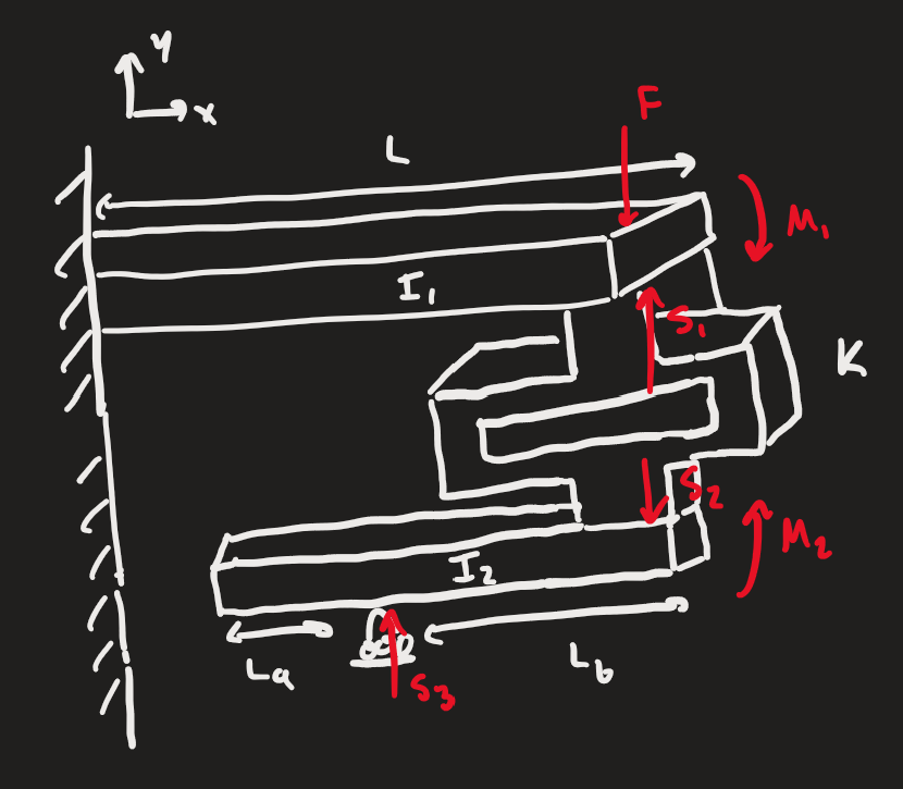
My specific goal was to design a beam configuration with linearly adjustable stiffness to enable precise stiffness control, simple enough to scale down to fit within a 14 mm diameter flexure. I evaluated several approaches analytically, including altering the angle between beams, changing beam cross-sections, and adjusting the contact position of a beam. I selected contact point adjustment for its scalability.
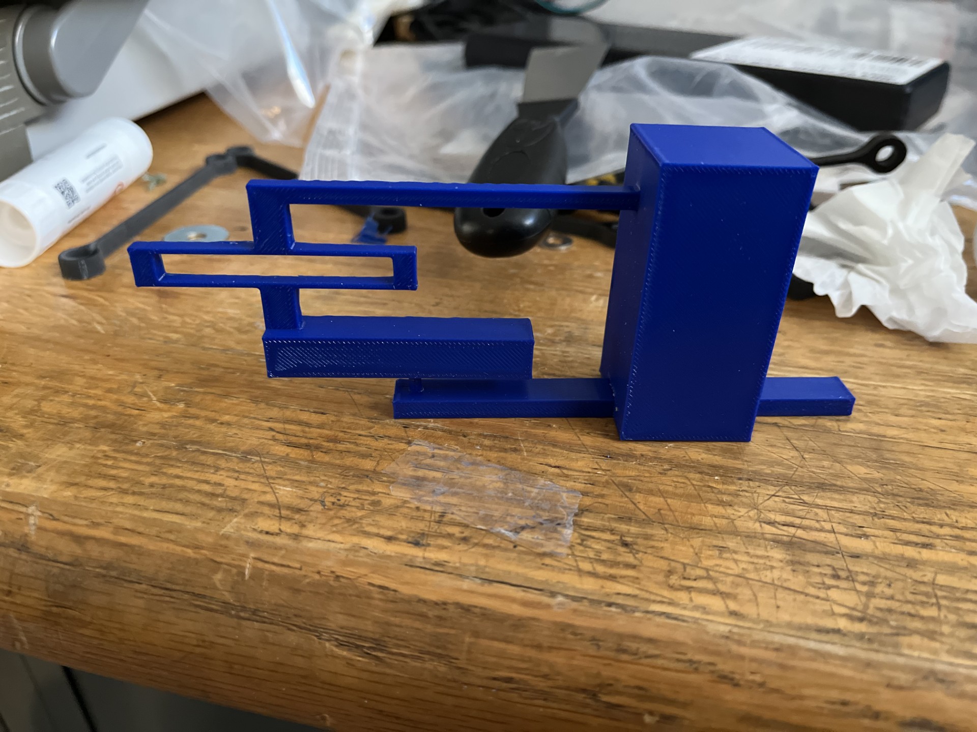
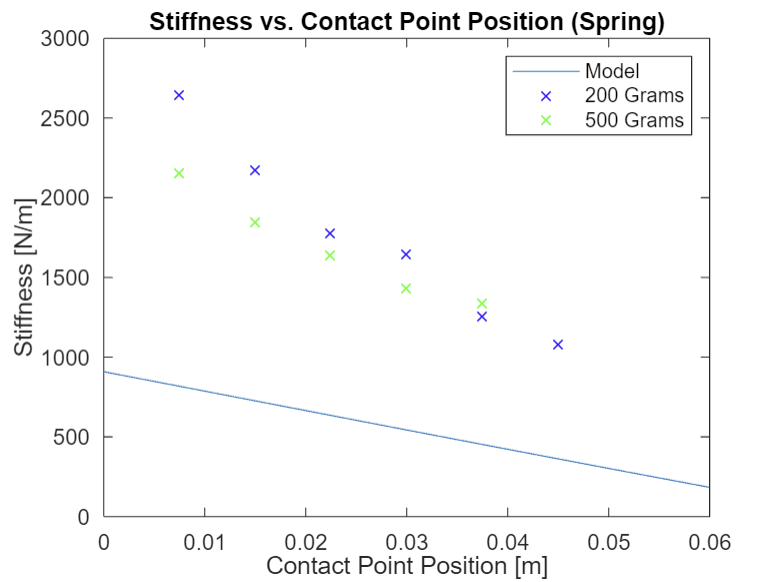
I developed a final design with an adjustable contact point and a linear spring connecting two beams, then optimized beam lengths, widths, and spring stiffness to produce a near-linear stiffness function. I CAD modeled and 3D printed a prototype to verify the analytical model, taking a series of measurements and confirming results with FEA analysis.
The analytical model was successfully verified, proving the viability of a variable stiffness configuration with an adjustable boundary condition. The concept was subsequently incorporated into the final flexure design.
Vacuum Chuck
A Carbide desktop mill was being used to machine flexures out of LDPE, a soft thin plastic, to a tolerance of ±0.001". I first designed and ran precision machining tests, varying speeds, feeds, and cutting depths to characterize the mill's achievable tolerance, which I measured at ±0.0025" — insufficient for the requirement. I then researched factors affecting precision, including tool wear, tool holding, and part holding, and identified part holding as the primary issue, as parts were previously secured with double-sided tape.
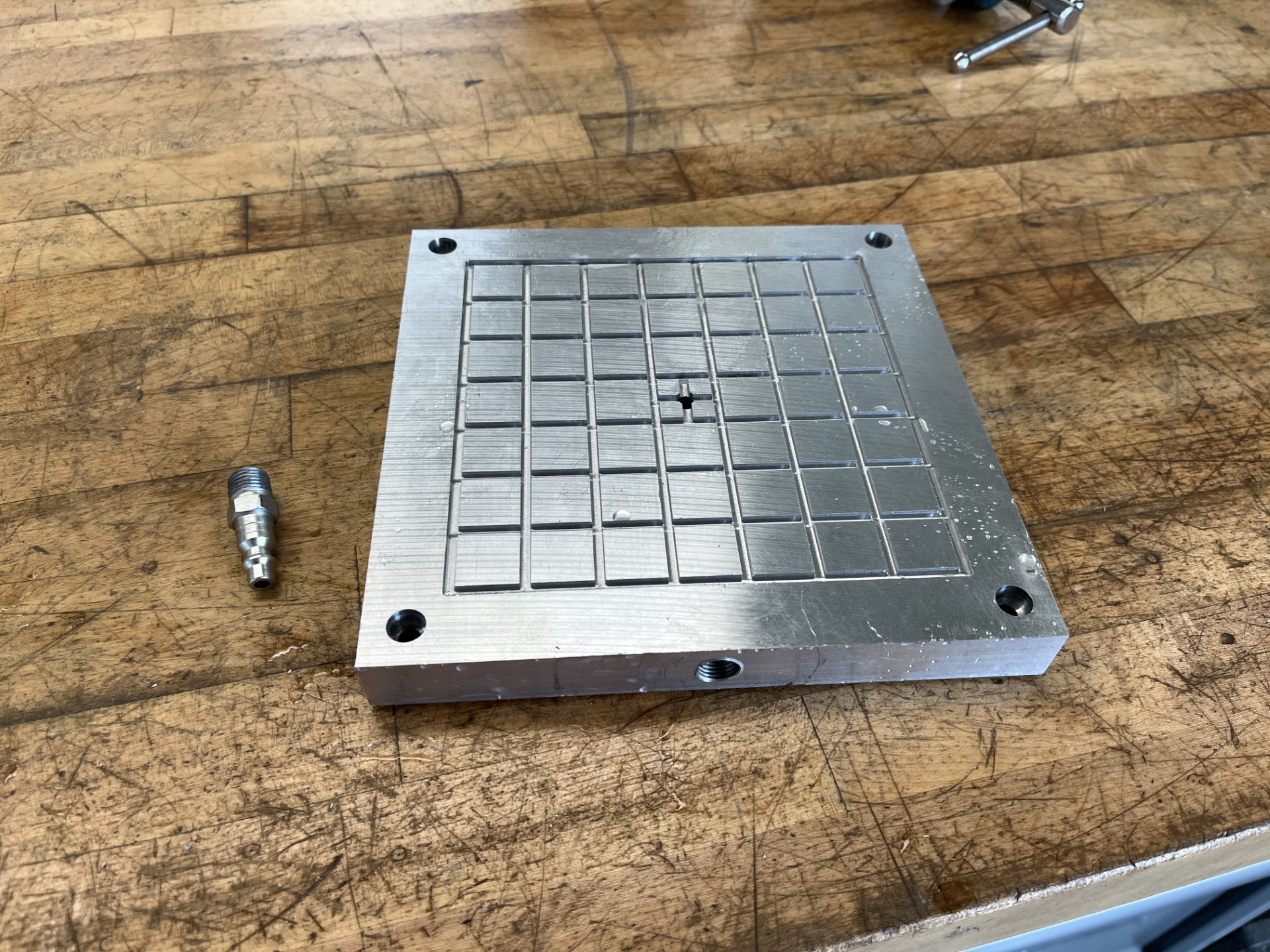
After researching part-holding options for thin stock, I determined that a vacuum chuck system would minimize part deflection and vibration during cutting while maximizing ease of use. I calculated the cutting forces on LDPE and determined the vacuum pressure and surface area required to counteract them. I then researched and purchased the components for a compressed air vacuum system, and CAD designed the vacuum board, optimizing the gasket groove layout to maximize available cutting area, with each isolated square sized to match one flexure. I machined the chuck on a manual mill.
I assembled and tested the system using the same precision test procedure and verified a tolerance within ±0.001". The system is now in use for flexure machining.